FEA Analysis Service
Finite Element Analysis (FEA)
- Comprehensive structure stress analysis
- Innovative engineering design and optimization
Email: [email protected]
Phone: 1-240-421-0756
Fax: 1-866-304-9034
Address: 15720 Brixham Hill Ave. Suite 300, Charlotte, NC USA 28277
What is FEA?
Finite Element Analysis (FEA) is a numerical simulation (computerized) method for predicting structure response to real-world load or testing conditions. Furthermore, the FEA simulation services can identify potential design issues, allowing for design or process changes at a very early stage. As a result, it saves project redesign and testing time, cost, and resources.
Our Mission:
- We offer affordable and professional FEA consulting services across a wide range of industry fields. Moreover, we specialize in various analysis types, including nonlinear, dynamic, vibration, thermal, drop test, fatigue, and stress analysis. By leveraging our expertise, we ensure accurate and reliable results tailored to your specific needs.
- Furthermore, we thoroughly evaluate structural performance to identify potential weaknesses or areas for improvement. As a result, we provide actionable suggestions to optimize the design, enhance efficiency, and ensure long-term reliability and safety.
What we need to determine the quote and run FEA simulation:
- 3D CAD model, or 2D drawings with all dimensional information.
- The detailed load condition.
- Material property for each component.
- Additionally, clarify your main concerns from the analysis.
What we provide on FEA project:
- A full, standard FEA analysis report including results, conclusions, comments, and suggestions.
- The FEA results include stress, strain, deflection, safety factor, reaction force, temperature, etc.
- Identification of potential design issues and actionable suggestions to optimize or improve the design.
- Furthermore, colorful images and animation files to enhance understanding.
- Q & A support for all your questions.
Our Engineering Services
Our FEA Analysis Service
Founded in 2005, FEAmax LLC brings over 20 years of experience in providing comprehensive Finite Element Analysis (FEA) Consultanting services. Based in Charlotte, NC, our office serves clients across the USA and globally, offering expert solutions that span the entire engineering process from initial design to final production. As a result, we deliver precise and reliable outcomes tailored to your specific project needs.
Furthermore, our services cater to a wide range of industries, including aerospace, automotive, manufacturing, civil engineering, and more. By leveraging advanced simulation techniques, we ensure optimal performance, safety, and cost-effectiveness in every project. Consequently, our clients benefit from streamlined processes and enhanced results.
In addition, partnering with FEAmax LLC provides access to an experienced team dedicated to excellence, innovation, and client satisfaction. Ultimately,contact us today to discover how we can support your engineering goals and deliver exceptional results.
Area Of Expertise
Static Analysis
- Static Linear Stress Analysis
- Geometric Nonlinear Analysis
- Material Nonlinear Analysis (creep, plasticity, hyper-elasticity, etc.)
- Contact Nonlinear Analysis (frictional contact)
Dynamic Analysis
- Seismic/Vibration Analysis
- Modal Analysis
- Harmonic Analysis
- Spectrum Analysis
- Transient Impact Analysis
- Fracture Analysis
Thermal Analysis
- Steady Thermal Analysis
- Transient Thermal Analysis
- Conduction Analysis
- Convection Analysis
- Radiation Analysis
- Phase Change Analysis
Other Analysis
- Fatigue Stress Analysis
- Buckling Analysis
- Electromagnetics Analysis
- Composite Analysis
- Acoustic Analysis
- Multiphysics Analysis
Introduction of FEA Analysis
What is FEM vs FEA?
The Finite Element Method (FEM) is fundamentally a numerical technique. Predominantly, it refers to the complex mathematical procedures used in an analysis solver. This method is strategically used to perform Finite Element Analysis (FEA) under any given load condition.
The Finite Element Method (FEM) is numerical technique extensively employed to perform Finite Element Analysis (FEA) of any given physical phenomenon.
What are the application fields of FEA?
FEA is extensively used across various industries, including mechanical, aerospace, automotive, construction, oil and gas, electronics, heavy equipment, sports, and bio-mechanics. For example, it plays a crucial role in designing machines, analyzing the fatigue life of parts, and evaluating load capacities for lifting cranes. Additionally, it is essential in constructing bridges and determining the crash or impact performance of vehicles. As a result, FEA continues to be a critical tool for engineers in solving complex problems and improving designs across many fields.
What are the advantages/benifits of FEA?
FEA functions as a virtual lab test conducted on a computer, allowing it to simulate and predict the behavior of structures with numerous advantages:
FEA tests real-world conditions on designs, predicting stress, deflection, safety factors, temperature, buckling deformation, fatigue, resonance frequency, fractures, and more.
It identifies and resolves potential design issues at a very early stage, thereby saving material, time, and costs.
FEA evaluates structural performance, uncovers design defects before creating prototypes, and provides valuable design guidance for engineers.
It optimizes product structures to achieve the best possible performance.
FEA enhances designs by offering better insights into critical parameters, contributing to a faster and more cost-effective design cycle.
Moreover, it is the best choice for scenarios where real lab tests are not feasible.
How many types of FEA are there?
The finite element method supports a wide variety of analysis types, each serving unique purposes. Below are the major types of FEA:
Static Structure Analysis: This includes both linear and nonlinear stress analysis. Furthermore, it provides valuable insights into structural stability under static loads.
Dynamic Analysis: This covers transient scenarios such as impact and drop tests. Additionally, it helps to predict behavior under time-varying conditions.
Vibration/Seismic Analysis: This involves modal, harmonic, and spectrum analyses. Consequently, it evaluates responses to vibrations and seismic events effectively.
Thermal Analysis: This includes steady-state and transient thermal studies. Moreover, it accounts for conduction, convection, and radiation effects.
Fatigue Analysis: This examines the durability of materials under repeated loading conditions. As a result, it helps to identify potential failure points early.
Linear/Nonlinear Buckling Analysis: This assesses the structural integrity against buckling under various load cases, ensuring reliable designs.
Electromagnetics Analysis: This evaluates electromagnetic field behaviors in complex systems. Consequently, it aids in optimizing electromagnetic designs.
Fracture Analysis: This helps in predicting crack propagation and failure mechanisms. Additionally, it supports improved material selection strategies.
Composite Analysis: This examines the performance and stability of composite materials under different conditions. Therefore, it ensures efficient material usage and enhanced performance.
What are the limitations/disadvantages of FEA?
FEA is a numerical simulation tool and an approximate method where the analysis is conducted on a virtual CAD model. However, all results are approximations, and users cannot precisely quantify or compare the differences between the obtained results and the real-world outcomes.
Moreover, several factors, such as simplified models, material data, load conditions, and stress concentrations, can lead to inaccuracies in the analysis results. Therefore, careful consideration is required to minimize potential errors.
In addition, FEA can be computationally expensive when solving complex problems. Furthermore, the cost of professional FEA software is often quite high, making it a significant investment for organizations.
Another challenge is that FEA can be difficult to learn and use. While short-term training may suffice for solving simple analysis projects, professional FEA software tends to be highly complex, with a wide range of options and capabilities. As a result, achieving expertise in FEA typically requires many years of learning and hands-on experience.
Finally, working on complicated FEA projects may demand specific resources, including an experienced FEA expert with extensive knowledge, access to professional FEA software, and a high-performance computer, among other necessities.
How to obtain accurate result from FEA?
To achieve accurate and reliable analysis results, it is essential to have substantial experience and knowledge of FEA, along with the use of professional FEA analysis software. Several key factors need careful consideration:
Stress Concentration or Singularity
These issues can arise from specific areas of the analysis model or the load conditions, such as sharp corners or concentrated point loads. Therefore, it is crucial to carefully check and verify the analysis results for maximum stress. Moreover, manual judgment plays an essential role during the analysis and post-processing stages.
Model Simplification
While simplifying the model is often necessary, it is important to ensure that the simplification does not compromise the accuracy of the results in the main areas of concern. Consequently, careful consideration is required during this step.
Material Data
Using simplified linear material data might lead to inaccuracies in the analysis. For specific projects, selecting appropriate nonlinear material data, such as bi-linear isotropic hardening models, hyper-elastic material data, or visco-elastic material data, may be required. Additionally, this choice significantly impacts the reliability of the results.
Load Conditions
The load conditions should closely replicate real-world testing scenarios. Furthermore, simplifying load and boundary conditions must be done cautiously to ensure reliability and accuracy in the analysis.
Meshing
The density, number, and type of mesh significantly influence the analysis results. As a result, careful meshing is essential to achieve reliable outcomes that meet project requirements.
Contact Conditions
Selecting the correct linear or nonlinear contact type in the analysis program is critical. Therefore, this step must be handled with precision to obtain accurate results.
Analysis Type and Solver
Nonlinear analyses, involving geometry, material, or contact, typically yield more accurate results. However, these analyses require significantly longer computation times. Consequently, proper planning is necessary to balance accuracy and efficiency.
What are the 10 most popular FEA software used by engineers?
The top suppliers of Finite Element Analysis (FEA) software include Autodesk, ANSYS, Dassault, MSC, COMSOL, ESI, SimScale, Altair, and others. Below is an overview of the most popular FEA software tools:
1. ANSYS
ANSYS is one of the most professional and widely used FEA software tools in the industry. It provides a complete package that includes structural, electromagnetic, and flow simulation capabilities. Additionally, ANSYS offers an integrated pre-processor, solver, and post-processor in a single package. Moreover, the ANSYS Workbench streamlines the process by coordinating all simulation data in one platform, making it easier to make informed design decisions.
2. ABAQUS
Renowned for its intuitive graphical user interface, ABAQUS is both powerful and widely used in research and industrial applications. It excels in handling contact, plasticity, and other nonlinear problems. Furthermore, ABAQUS supports Python scripting, which offers users great flexibility in their analyses. The product suite includes five core tools: Abaqus/CAE, Abaqus/Standard, Abaqus/Explicit, Abaqus/CFD, and Abaqus/Electromagnetic.
3. COMSOL Multiphysics
COMSOL is known for its seamless integration with tools like MATLAB™, Java™, and Autodesk™ Inventor. As a result, it is widely adopted for solving a wide variety of analysis problems. Additionally, it offers tools for electrical applications, fluid mechanics, static and dynamic systems, chemical processes, and acoustics.
4. MSC Nastran/Patran
Originally created by NASA, MSC Nastran provides a range of linear, nonlinear, steady-state, and transient analysis options. Specifically, Nastran serves as a solver, focusing on structural and vibration analyses, while Patran handles pre- and post-processing. Therefore, this combination is particularly effective for dynamic problems, beam and 2D analyses, and aerospace applications.
5. SimScale
SimScale is a cloud-based FEA software that offers tools for thermal, CFD, and general mechanical analyses. Because of its cloud-based nature, users can perform accurate calculations without needing in-depth knowledge of tensors, matrices, or integrals. Consequently, it is considered an accessible alternative to ANSYS.
6. OpenFOAM
This open-source FEA software is completely free and widely used in academia and industry. Furthermore, OpenFOAM focuses on computational fluid dynamics (CFD) and provides cost-effective, scientifically accurate solutions for designing, testing, and fabricating systems. Thus, it is particularly beneficial for the oil and gas industry.
7. LS-DYNA
Developed by Livermore Software Technology Corporation (now part of ANSYS), LS-DYNA is a highly advanced tool for nonlinear and large deformation analyses. Specifically, it is powerful for explicit dynamic analyses, including transient, impact, and drop tests. Consequently, industries such as automotive, aerospace, construction, military, and bioengineering rely heavily on LS-DYNA.
8. AutoDesk CFD
Autodesk provides a CFD module that integrates seamlessly into existing designs. As a result, users can adjust input parameters without needing detailed knowledge of the project. This makes it particularly user-friendly and efficient for fluid system simulations.
9. Hypermesh
Provided by Altair Engineering Inc., Hypermesh is a powerful pre-processing tool for multiphysics applications. It specializes in creating effective meshes for FEA analysis. Additionally, it allows users to define custom meshes for specific purposes. While it focuses on meshing, it integrates well with other FEA solvers for conducting analyses.
10. FEA Modules in CAD Software
Many CAD software packages, such as SolidWorks Simulation, Creo Simulation, and Inventor Nastran, include built-in FEA modules. These tools are effective for solving simple to moderately complex FEA problems. However, for highly complicated projects, professional FEA tools remain the better choice.
11. Other FEA Software
Additional tools include SAMCEF, ADINA, IVRESS, and COSMOS, which provide specialized capabilities for specific applications.
What are the steps to run FEA?
Finite Element Analysis (FEA) involves several crucial steps that must be followed systematically to ensure accurate and reliable results:
Step 1 – Pre-processing
First and foremost, begin by creating the CAD model. Furthermore, simplify the model as needed and input it into the FEA program. Then, assign the appropriate material data to the model to ensure proper setup.
Step 2 – Define contact connections
Next, carefully select the correct connection type for each pair of contacts. This step is essential to accurately represent the interactions between different components and maintain structural integrity.
Step 3 – Meshing the model
After defining the connections, choose the correct mesh type and ensure sufficient mesh density in the main areas of concern. Consequently, this step plays a critical role in achieving accurate and reliable results.
Step 4 – Select analysis type and solver
At this stage, identify the appropriate analysis type, such as static or dynamic, and decide whether the problem requires linear or nonlinear analysis. Moreover, selecting the correct solver is vital for accurate results.
Step 5 – Apply loads and boundary conditions
Carefully apply the load and boundary conditions to reflect real-world scenarios. Additionally, always consider the worst-case conditions to ensure safety, reliability, and durability of the structure.
Step 6 – Run the analysis
Once all parameters are set, proceed to execute the simulation to compute results based on the defined setup and conditions.
Step 7 – Review and verify results
After running the analysis, thoroughly analyze and verify the results to confirm they align with expectations. If necessary, make adjustments to enhance accuracy and consistency.
Step 8 – Prepare the formal FEA report
Finally, compile a detailed and comprehensive report that includes the job description, parameter settings, results, conclusions, comments, and suggestions. Ultimately, this report serves as the final deliverable for the analysis.
How to start with FEA (Steps to Learn FEA for General Use)?
To learn FEA for general use on simple and moderately complex projects, product and design engineers should follow these steps:
Understand the Fundamentals
First, take classes on FEA theory to understand the general concepts of structural mechanics and materials. These foundational principles are essential for success.
Participate in Training
Next, participate in a one- or two-week training class on FEA analysis software to familiarize yourself with the tools and their capabilities.
Solve Simple Problems
Afterward, start by solving simple problems to build confidence and a better understanding of the process.
Consistent Practice
Additionally, practice consistently and seek guidance from instructors and peers to refine your skills.
Apply Insights
Finally, use simple FEA applications to gain valuable insights and address design issues quickly and efficiently.
Steps to Become an FEA Specialist
To become an FEA specialist capable of solving complicated problems, more advanced learning and tools are required:
Build a Strong Foundation
First, begin with a strong educational background in mathematics, mechanics, physics, and materials science.
Deepen Mathematical Understanding
Additionally, develop a solid understanding of related mathematical concepts, including linear and tensor algebra, differential calculus, and integral calculus.
Take Advanced Classes
Then, take in-depth classes on FEA theory across various application fields to fully grasp the underlying principles of FEA programs.
Expand Practical Knowledge
Moreover, attend training classes on FEA software, focusing on different types of analysis, to expand your practical knowledge.
Understand Theory and Techniques
Importantly, focus not only on learning the software but also on understanding the theory and modeling techniques behind it.
Gradual Progression
Subsequently, start with simpler problems and gradually progress to more complex scenarios, consistently practicing and learning from instructors and peers.
Correlate Results
Furthermore, correlate FEA results with physical testing outcomes to gain experience and improve the accuracy of future analyses.
Patience and Persistence
Finally, be patient and persistent, as becoming a specialist requires significant time, effort, and practice.
FEA Analysis Project Showcase
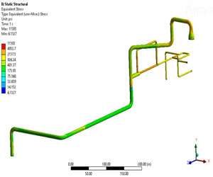
Seismic Stress Analysis
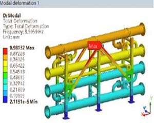
Performed a detailed modal and vibration stress analysis on a pipe cage model affixed to a level surface, simulating seismic conditions representative of a seismic zone 4 area. The primary goal was to identify regions of high stress concentration and evaluate the structural response of the piping when it stood independently, without connections to other CDU modules. Using advanced Finite Element Analysis (FEA), the study predicted the structural behavior under earthquake spectrum loads, pinpointed potential weak points, and assessed the overall performance and safety of the structure.
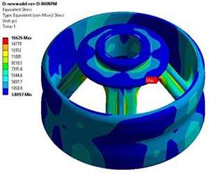
Fatigue Stress Analysis
Thermal Analysis
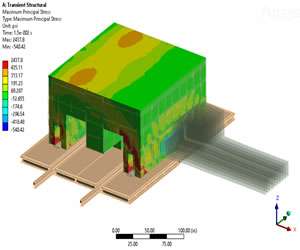
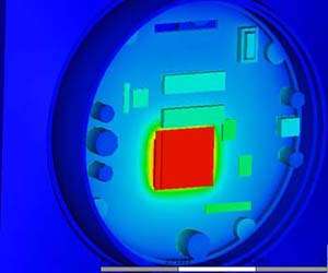
The heat source within a microchip structure can generate transient high temperatures, resulting in substantial thermal deformation and stress. To address this, we conducted a Finite Element Analysis (FEA) transient thermal stress assessment on the microchip structure. This analysis accurately determined temperature, deflection, and stress distribution across various time intervals. FEA thermal analysis is particularly valuable when the goal is to evaluate detailed temperature distribution, understand thermal stress behavior, or analyze structural responses under well-defined boundary conditions. These insights guide critical design improvements and ensure reliable performance.
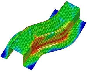
Metal Forming Analysis
FEAmax provides a comprehensive range of metal forming simulation services, covering diverse processes such as die casting, stamping, hydraulic forming, tube bending, and heat treatment, among others. Moreover, our specialized, on-demand forming simulations are tailored to help you virtually test and validate your metal tooling designs with precision. By leveraging these advanced simulations, you can effectively minimize the risk of real-world failures, thereby saving valuable time, effort, and resources. Consequently, this innovative approach enhances operational efficiency, ensures higher reliability, and supports a more cost-effective design and production process.
Piping Stress Analysis